


Research Applications Technology Team
Park Systems, HQ, Suwon, Republic of Korea
Lateral Force Microscopy (LFM) is a practical AFM-based approach for visualizing atomic-lattice features under ambient conditions when the tip–sample interaction and imaging conditions are carefully controlled2,3. In this application note, we present LFM-based atomic-lattice imaging of Highly Oriented Pyrolytic Graphite (HOPG) using a Park Systems AFM and discuss practical factors that influence lattice visibility, including scan rate, tip–sample contact condition, measurement angle, tip condition, and system noise floor3,9. Building on prior studies of atomic-lattice imaging by AFM, this note provides an application-focused overview of how clear lattice contrast can be obtained and verified through FFT- and PSD-based analyses. The measured lattice periodicity was consistent with the known graphite lattice, demonstrating the usefulness of LFM as a practical method for atomic-lattice visualization on suitable reference samples.
Summary of the Prior Work (Atomic-Lattice Imaging by LFM Using a NX10 System)
The prior study1 reported that Lateral Force Microscopy (LFM) implemented on a Park Systems NX10 AFM can image atomic lattices of two-dimensional (2D) materials and even moiré superlattices under ambient conditions. This work shows that LFM can be used to routinely measure atomic-scale features.
1.1 Background and Objective
As research on van der Waals materials and heterostructures advances rapidly, the demand for non-destructive structural analysis at the atomic scale has increased. While Scanning Tunneling Microscopy (STM) and Transmission Electron Microscopy (TEM) can provide atomic resolution, STM requires the entire scanned surface to be electrically conductive and contacted while TEM requires ultra-high vacuum and specialized sample preparation to achieve an ultra-thin layer mounted on a grid2,3. AFM-based approaches overcomes these limitations because they are non-destructive and require no electrical contact or special sample preparation beyond a surface free of significant contamination. This application note provides a robust protocol for stable atomic-lattice visualization under ambient conditions on Park Systems AFMs, with examples taken from an NX10.
1.2 Methods (Ambient LFM Protocol)
The authors used LFM to measure nanoscale friction signals and optimized the following parameters to achieve atomic-scale imaging3,7,9:
1. Image parameters, including scan size and feedback gain.
2. Scan rate, with relatively high scan rates used to reduce the influence of thermal drift.
3. Tip–sample interaction and probe condition, including contact force and cantilever selection.
1.3 Key Results
• Scan rate: With the overscan set to its maximum, the scan rate was varied during measurements. Atomic lattices were observed in the range of 15–35 Hz, with the clearest lattice appearing at approximately 21 Hz, which was favorable for mitigating thermal drift9.
• Contact force: The most distinct hexagonal lattice was obtained at a low setpoint (reported as 6.68 nN). Increasing the setpoint led to lattice distortion2,7.
• Applicability: Atomic structures of graphene and transition metal dichalcogenides (TMDs) were imaged3,4. The atomic structure at torn or self-folded graphene edges was also analyzed, with the armchair direction predominantly observed.
• Moiré superlattice: a moiré pattern was successfully imaged in a graphene/hBN heterostructure.
• Analysis: Fourier-transform-based analysis enabled quantification of lattice periodicity and lattice constant, and provided information relevant to moiré periodicity and twist angle estimation11, although moiré periodicity can also be influenced by strain and lattice relaxation12.
1.4 Significance
This work provides a practical protocol for acquiring atomic-lattice images of 2D materials under ambient conditions using LFM3. Based on these findings, we applied the same LFM-based approach to HOPG. Before presenting our results, we summarize the mechanism of achieving atomic resolution in contact/LFM AFM.
Principle of Atomic-Lattice Imaging by AFM (Contact/LFM Perspective)
High-resolution AFM imaging is enabled by interactions between the outermost atom at the tip apex and atoms on the sample surface2,3. Although the macroscopic tip radius of curvature is typically larger than 10 nm, the dominant contribution to the measured signal arises from atomic-scale interactions localized at the tip apex2.
The primary factors that allow AFM to image atomic lattices are as follows:
1. Dominant interaction from the outermost apex atom.
Regardless of the overall tip geometry, the effective interaction with the surface is governed primarily by the outermost atom at the tip apex, enabling atomic-scale spatial resolution.
2. Nonlinearity of interatomic forces.
The tip–sample interatomic force varies nonlinearly with distance. In certain distance regimes, the contribution of the apex atom becomes relatively enhanced, which can improve the effective resolution.
3. Precise feedback control.
A high-performance feedback system detects and controls cantilever deflection with high precision. This enables fine positioning of the probe and supports atomic-resolution imaging.
Despite these factors, contact-mode scanning (especially LFM) can suffer from friction- and drive-related disturbances that degrade image quality. A representative example is the stick–slip phenomenon.
Disturbance Factor: Stick–Slip and Practical Limitations in LFM Images
Stick–slip typically occurs when static friction exceeds kinetic friction. A larger force is required to initiate motion, causing the tip to alternately adhere to the surface (“stick”) and then suddenly slide (“slip”) once a threshold is reached. Repetition of this process can introduce irregular patterns in LFM images, distorting or obscuring the atomic-lattice signal7,8.
In addition to stick–slip artifacts, practical limitations such as the vertical and lateral noise floor, scanner stability, surface contamination, and sample preparation can affect the ability to obtain atomic-lattice contrast. In this context, LFM can be more sensitive to atomic-scale lateral variations than conventional height imaging, while being less restrictive than electrical or force-modulation-based approaches such as Conductive AFM or Torsional Force Microscopy (TFM). Therefore, stable imaging conditions and a clean, well-prepared surface are essential for reliable LFM-based atomic-lattice imaging.
Sample: Highly Oriented Pyrolytic Graphite (HOPG)
HOPG was used as the reference sample for atomic-lattice measurements. It consists of stacked graphene layers, each of which forms a two-dimensional lattice in which carbon atoms are arranged in a hexagonal honeycomb structure5,6. For this reason, HOPG is widely used as a benchmark sample for atomic-resolution imaging. In addition to being inexpensive, chemically stable, conductive, and well studied, HOPG can be readily cleaved along its basal planes, thereby exposing a very smooth and clean surface. The lattice constant of graphene is known to be approximately 0.246 nm, which facilitates validation of the measured results5-7.
These properties, together with its resistance to contamination and surface stability under ambient conditions, are advantageous for ensuring experimental reproducibility6,7.
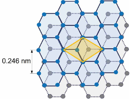
Figure 1 / Atomic structure of Highly Oriented Pyrolytic Graphite (HOPG).
Schematic illustration of the graphene honeycomb lattice that forms the HOPG surface.
The primitive unit cell and lattice constant of graphene, a = 0.246 nm, are indicated.
Resolution Optimization
Atomic-lattice imaging requires the establishment of stable measurement conditions. Before attempting lattice imaging, the vertical noise floor of the system was evaluated by a zero-scan measurement, yielding a value of 0.23 Å (23 pm). We varied experimental conditions including cantilever type, scan rate, scan size, tip velocity, setpoint, Z feedback gains, XY servo gains and scan angle and found the following parameters to be most critical:
1. Scan rate control.
Scan rate affects the stability of atomic-lattice imaging because it determines the image acquisition time and the extent to which thermal drift can influence the measured lattice. A relatively high scan rate can help reduce drift-related distortion, but the appropriate value depends on the scan size, imaging conditions, and system response. Therefore, the scan rate should be adjusted for each measurement condition9.
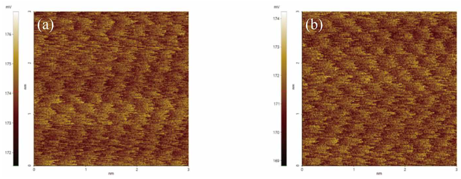
Figure 2 / Comparison of HOPG atomic-lattice images obtained under different scan rate conditions.
(a) Image acquired at 15 Hz, and (b) image acquired at 20 Hz.
2. Adjustment of tip–sample contact condition.
Adjusting the contact condition between the tip and the sample is important for reducing unstable interactions during LFM measurements. Excessive contact force may disturb the lattice signal, whereas insufficient contact may reduce the stability of the lateral force signal. Therefore, the setpoint should be adjusted together with the cantilever properties and feedback conditions to obtain stable lattice contrast3,7.
3. Adjustment of measurement angle.
The relative angle between the scan direction and the lattice direction of the sample also affects the visibility of atomic-lattice contrast in LFM images. When the scan direction is appropriately selected with respect to the lattice orientation, the lattice-related signal can become clearer, contributing to more stable and reproducible imaging10.
We also found that the tip condition had a greater impact on image quality than the specific tip model or type. In this study, measurements were primarily conducted using tips with relatively low spring constants (e.g., Spark 70, NSC, FMR, and CONTSCR). Differences among tip types were less critical than the measurement conditions and the tip condition. Under optimized conditions, the lateral signal was maximized.
To quantitatively verify the atomic lattice periodicity, a PSD-based lattice analysis was performed.
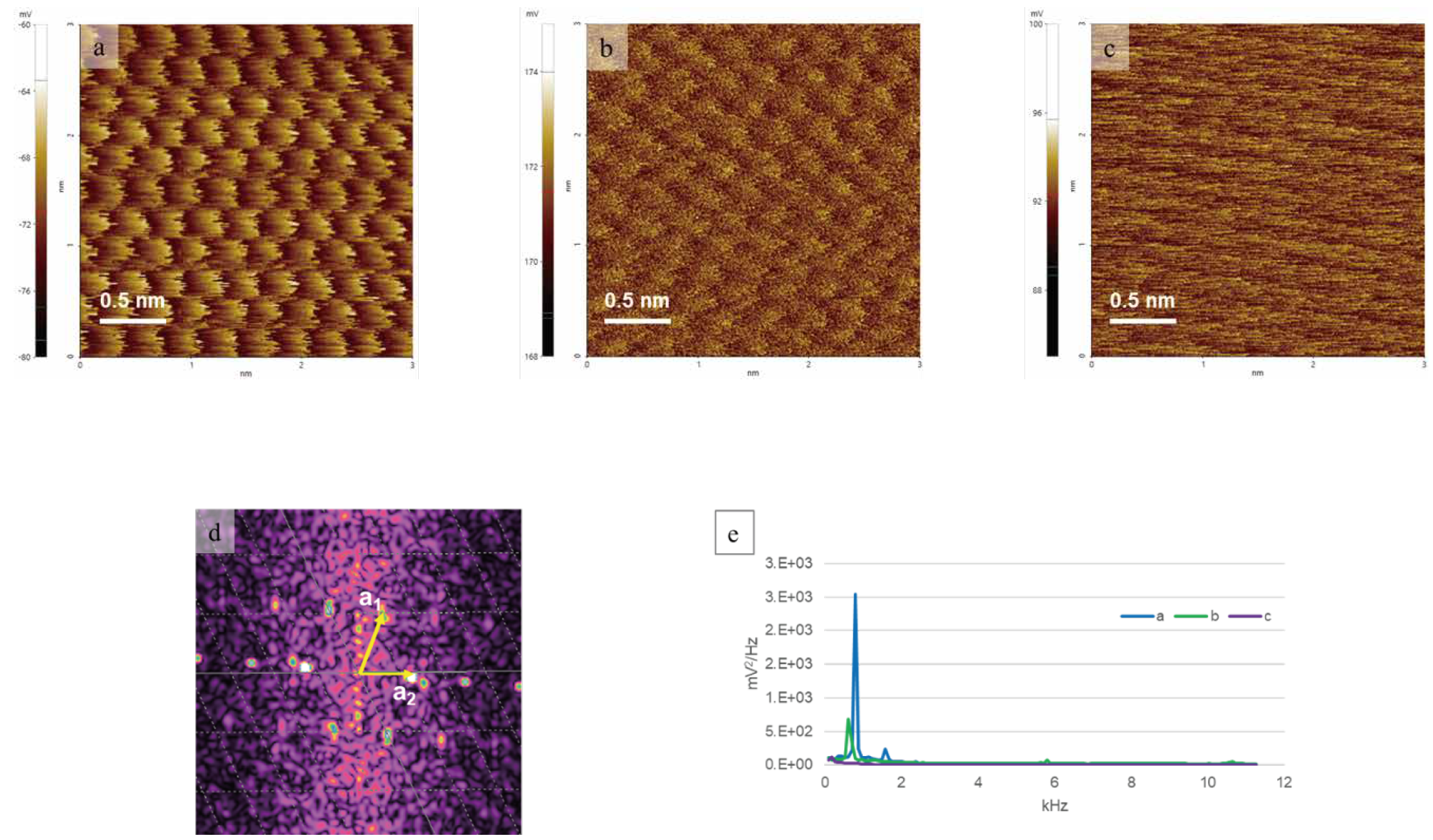
Figure 3 / Fast Fourier Transform (FFT)-based lattice analysis of the HOPG atomic lattice obtained from a 3 nm scan area.
(a–c) Representative atomic-lattice images acquired at different scan rates: (a) 18 Hz, (b) 15 Hz, and (c) 7 Hz. The same setpoint was used for all three measurements. The scan angle was manually adjusted during imaging and is therefore not presented as a quantitative parameter. The lattice pattern is most clearly resolved in (a), remains visible but less distinct in (b), and becomes significantly degraded in (c). (d) FFT image calculated from (a), showing a hexagonal reciprocal lattice pattern. (e) PSD spectrum derived from the FFT signal, used as a supplementary indication of lattice-related periodicity.
The lattice vectors obtained from the spectral analysis show lengths of approximately 0.20 nm and 0.25 nm, with an angle of approximately 65° between them. These values are close to the graphite lattice constant (~0.246 nm) and the characteristic 60° angle of the hexagonal lattice, confirming the hexagonal atomic lattice structure of HOPG5–7,11.
Results and Conclusion
In this experiment, we confirmed the feasibility of LFM-based atomic-lattice imaging of HOPG under small-scan conditions. These results show that clear lattice contrast can be obtained when key measurement factors, such as scan rate, tip–sample contact condition, measurement angle, tip condition, and system noise floor, are carefully controlled1. FFT- and PSD-based analyses supported the observed lattice periodicity, and the extracted lattice vectors were consistent with the known graphite lattice structure5-7. Overall, this application note provides a practical reference for obtaining and verifying atomic-lattice contrast using LFM under ambient conditions.
References
- Kim, S.; Moon, D.; Jeon, B.R.; Yeon, J.; Li, X.; Kim, S. "Accurate Atomic-Scale Imaging of Two-Dimensional Lattices Using Atomic Force Microscopy in Ambient Conditions." Nanomaterials 2022, 12, 154.
- Giessibl, F.J. "AFM’s path to atomic resolution." Mater. Today 2005, 8, 32–41.
- Gan, Y. "Atomic and subnanometer resolution in ambient conditions by atomic force microscopy." Surf. Sci. Rep. 2009, 64, 99–121.
- Novoselov, K.S. et al. "2D materials and van der Waals heterostructures." Science 2016, 353, aac9439.
- Sugawara, Y. et al. "Simultaneous Observation of Atomically Resolved AFM/STM Images of a Graphite Surface." Jpn. J. Appl. Phys. 1990, 29, L157–L159.
- Sugawara, Y.; Ishizaka, T.; Morita, S. "Scanning force/tunneling microscopy of a graphite surface in air." J. Vac. Sci. Technol. B 1991, 9, 1092–1095.
- Ruan, J.A.; Bhushan, B. "Atomic-scale and microscale friction studies of graphite and diamond using friction force microscopy." J. Appl. Phys. 1994, 76, 5022–5035.
- Mate, C.M. et al. "Atomic-scale friction of a tungsten tip on a graphite surface." Phys. Rev. Lett. 1987, 59, 1942–1945.
- Kim, S.; Kim, S. "Gain and Scan Rate Dependence of Friction at the Nanoscale Measured by Lateral Force Microscopy." J. Korean Phys. Soc. 2018, 73, 388–391.
- Marsden, A.J. et al. "Friction force microscopy: A simple technique for identifying graphene on rough substrates and mapping the orientation of graphene grains on copper." Nanotechnology 2013, 24, 255704.
- Eaton, P.; West, P. "AFM image processing and analysis." In Atomic Force Microscopy; Oxford University Press: Oxford, UK, 2010; pp. 103–120.
- Halbertal, D. et al. "Moiré Metrology of Energy Landscapes in van der Waals Heterostructures." Nature Communications 2021, 12, 242.


